- 您现在的位置:买卖IC网 > Sheet目录3850 > AT89C51RB2-3CSIM (Atmel)IC 8051 MCU FLASH 16K 40DIP
39
AT89C51RB2/RC2
4180E–8051–10/06
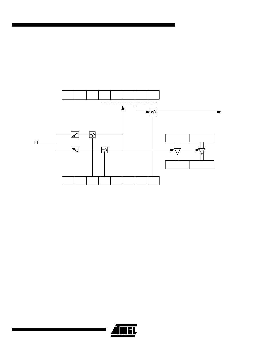
PCA Capture Mode
To use one of the PCA Modules in the capture mode either one or both of the CCAPM
bits CAPN and CAPP for that Module must be set. The external CEX input for the Mod-
ule (on port 1) is sampled for a transition. When a valid transition occurs the PCA
hardware loads the value of the PCA counter registers (CH and CL) into the Module's
capture registers (CCAPnL and CCAPnH). If the CCFn bit for the Module in the CCON
SFR and the ECCFn bit in the CCAPMn SFR are set then an interrupt will be generated
(see Figure 13).
Figure 13. PCA Capture Mode
CF
CR
CCON
0xD8
CH
CL
CCAPnH
CCAPnL
CCF4 CCF3
CCF2
CCF1
CCF0
PCA IT
PCA Counter/Timer
ECOMn
CCAPMn, n = 0 to 4
0xDA to 0xDE
CAPNn MATn TOGn PWMn ECCFn
CAPPn
Cex. n
Capture
发布紧急采购,3分钟左右您将得到回复。
相关PDF资料
PIC16C72A-04/SO
IC MCU OTP 2KX14 A/D PWM 28SOIC
AT89C51ID2-RLTIM
IC 8051 MCU FLASH 64K 44VQFP
AT89C51IC2-SLSIL
IC 8051 MCU FLASH 32K 44PLCC
AT89C51CC03U-RLTIM
IC 8051 MCU FLASH 64K 44VQFP
PIC24EP64MC204-I/PT
MCU 16BIT 64KB FLASH 44TQFP
AT89C51CC03U-RDTIM
IC 8051 MCU FLASH 64K 64VQFP
AT89C51CC03U-7CTIM
IC 8051 MCU FLASH 64K 64BGA
AT89C51CC03C-S3SIM
IC 8051 MCU FLASH 64K 52PLCC
相关代理商/技术参数
AT89C51RB2-3CSUL
功能描述:8位微控制器 -MCU 8-bit 16K Flash C51RB2 RoHS:否 制造商:Silicon Labs 核心:8051 处理器系列:C8051F39x 数据总线宽度:8 bit 最大时钟频率:50 MHz 程序存储器大小:16 KB 数据 RAM 大小:1 KB 片上 ADC:Yes 工作电源电压:1.8 V to 3.6 V 工作温度范围:- 40 C to + 105 C 封装 / 箱体:QFN-20 安装风格:SMD/SMT
AT89C51RB2-3CSUM
功能描述:8位微控制器 -MCU C51RB2 FLASH 5V 16k ind RoHS:否 制造商:Silicon Labs 核心:8051 处理器系列:C8051F39x 数据总线宽度:8 bit 最大时钟频率:50 MHz 程序存储器大小:16 KB 数据 RAM 大小:1 KB 片上 ADC:Yes 工作电源电压:1.8 V to 3.6 V 工作温度范围:- 40 C to + 105 C 封装 / 箱体:QFN-20 安装风格:SMD/SMT
AT89C51RB2L1-RLTUL
功能描述:8位微控制器 -MCU Microcontroller
RoHS:否 制造商:Silicon Labs 核心:8051 处理器系列:C8051F39x 数据总线宽度:8 bit 最大时钟频率:50 MHz 程序存储器大小:16 KB 数据 RAM 大小:1 KB 片上 ADC:Yes 工作电源电压:1.8 V to 3.6 V 工作温度范围:- 40 C to + 105 C 封装 / 箱体:QFN-20 安装风格:SMD/SMT
AT89C51RB2-RLRIL
功能描述:IC MCU FLASH 8051 16K 3V 44-VQFP RoHS:否 类别:集成电路 (IC) >> 嵌入式 - 微控制器, 系列:89C 标准包装:1,500 系列:AVR® ATtiny 核心处理器:AVR 芯体尺寸:8-位 速度:16MHz 连通性:I²C,LIN,SPI,UART/USART,USI 外围设备:欠压检测/复位,POR,PWM,温度传感器,WDT 输入/输出数:16 程序存储器容量:8KB(4K x 16) 程序存储器类型:闪存 EEPROM 大小:512 x 8 RAM 容量:512 x 8 电压 - 电源 (Vcc/Vdd):2.7 V ~ 5.5 V 数据转换器:A/D 11x10b 振荡器型:内部 工作温度:-40°C ~ 125°C 封装/外壳:20-SOIC(0.295",7.50mm 宽) 包装:带卷 (TR)
AT89C51RB2-RLRIM
功能描述:IC MCU FLASH 8051 16K 5V 44-VQFP RoHS:否 类别:集成电路 (IC) >> 嵌入式 - 微控制器, 系列:89C 产品培训模块:MCU Product Line Introduction
AVR® UC3 Introduction 标准包装:2,500 系列:AVR®32 UC3 B 核心处理器:AVR 芯体尺寸:32-位 速度:60MHz 连通性:I²C,IrDA,SPI,SSC,UART/USART,USB 外围设备:欠压检测/复位,DMA,POR,PWM,WDT 输入/输出数:28 程序存储器容量:128KB(128K x 8) 程序存储器类型:闪存 EEPROM 大小:- RAM 容量:32K x 8 电压 - 电源 (Vcc/Vdd):1.65 V ~ 1.95 V 数据转换器:A/D 6x10b 振荡器型:内部 工作温度:-40°C ~ 85°C 封装/外壳:48-TQFP 包装:带卷 (TR) 配用:ATSTK600-TQFP48-ND - STK600 SOCKET/ADAPTER 48-TQFPATAVRONEKIT-ND - KIT AVR/AVR32 DEBUGGER/PROGRMMRATEVK1101-ND - KIT DEV/EVAL FOR AVR32 AT32UC3B 其它名称:AT32UC3B1128-AUR-NDAT32UC3B1128-AURTR
AT89C51RB2-RLRUL
功能描述:8位微控制器 -MCU C51RB2 FLASH 3V 16k ind RoHS:否 制造商:Silicon Labs 核心:8051 处理器系列:C8051F39x 数据总线宽度:8 bit 最大时钟频率:50 MHz 程序存储器大小:16 KB 数据 RAM 大小:1 KB 片上 ADC:Yes 工作电源电压:1.8 V to 3.6 V 工作温度范围:- 40 C to + 105 C 封装 / 箱体:QFN-20 安装风格:SMD/SMT
AT89C51RB2-RLRUM
功能描述:8位微控制器 -MCU C51RB2 FLASH 5V 16k ind RoHS:否 制造商:Silicon Labs 核心:8051 处理器系列:C8051F39x 数据总线宽度:8 bit 最大时钟频率:50 MHz 程序存储器大小:16 KB 数据 RAM 大小:1 KB 片上 ADC:Yes 工作电源电压:1.8 V to 3.6 V 工作温度范围:- 40 C to + 105 C 封装 / 箱体:QFN-20 安装风格:SMD/SMT
AT89C51RB2-RLTCM
制造商:ATMEL 制造商全称:ATMEL Corporation 功能描述:8-bit Microcontroller with 16K/ 32K Bytes Flash